
Expected Outcome Defined
Establishing rigorous dimensional baselines, tolerance boundaries, and functional target envelopes before launching additive manufacturing batches.
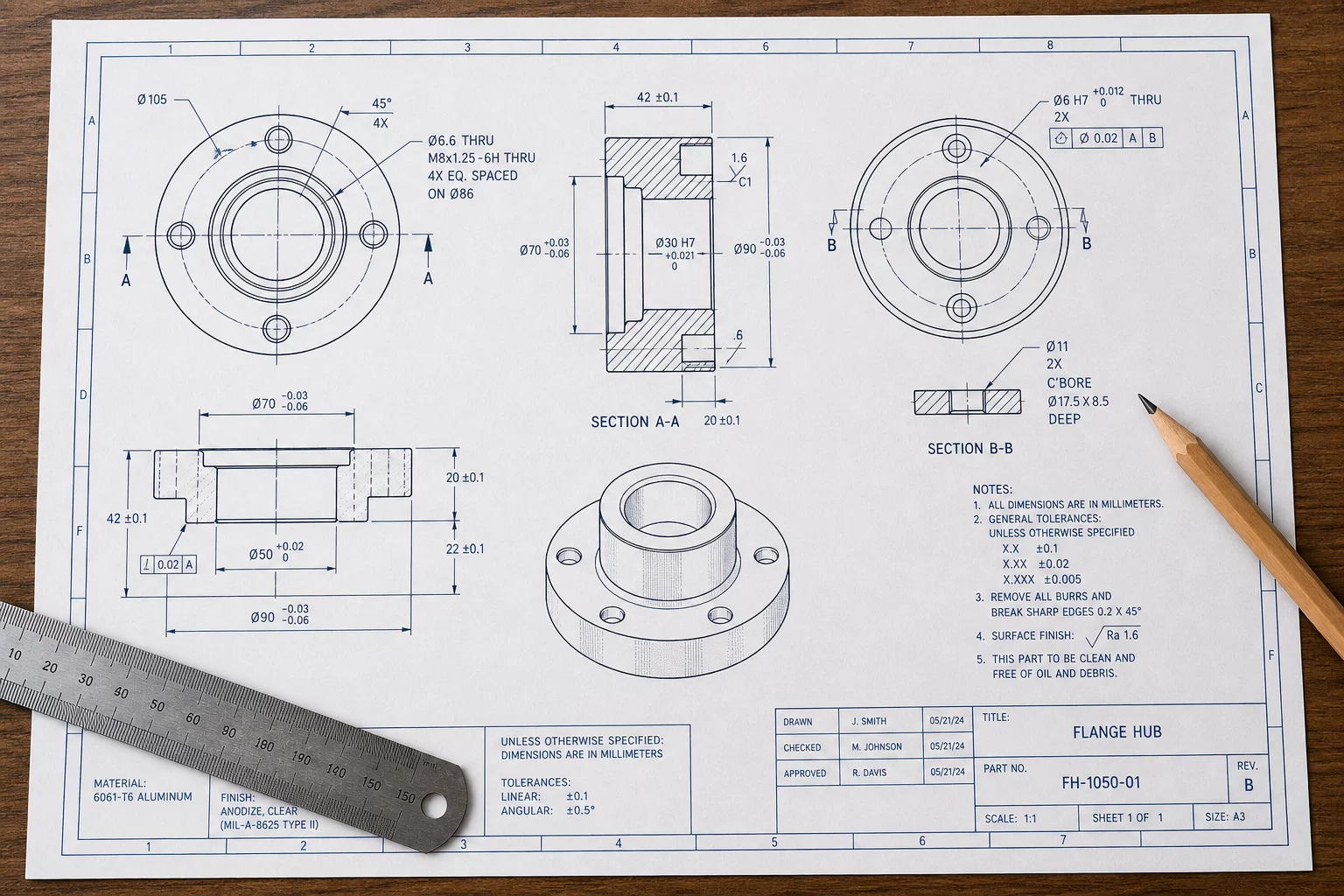
Evaluation Scope and Metrological Standards
Setting an unambiguous baseline is the cornerstone of repeatable additive manufacturing. When evaluating batches produced across multiple print beds or print runs, engineers often confuse the output of a single "hero part" with a stable process capability. Defining the expected outcome requires pinning down exact nominal dimensions, determining symmetric or asymmetric tolerance bands according to functional mating requirements, and establishing the reference coordinate frames for all subsequent metrological passes. Without this predefined baseline, subsequent inspection data yields statistical noise rather than actionable process control.
Every manufacturing run experiences systematic and random variations, from thermal fluctuations across the build plate to microscopic feeder motor micro-stepping deviations. By defining the expected geometric and mechanical boundaries upfront, production teams eliminate guesswork during post-print verification. This protocol provides a practical framework for establishing nominal reference models, selecting critical-to-quality (CTQ) features, and setting statistical process control thresholds that balance precision engineering against real-world production throughput.
Fieldbook Inspection Benchmark
Statistical process control relies on repeatability across all batch specimen samples rather than a single ideal part. Ensure consistent thermal bed calibration and optical micrometer zero-points before taking measurement passes.
Process Variation Breakdown
A robust expected outcome specification separates cosmetic tolerances from critical functional interfaces. While aesthetic surfaces may accommodate variations up to ±0.15mm without degrading consumer acceptance, snap fits, dowel bores, and bearing seats demand rigorous conformance within ±0.03mm. Tracking these distinct zones prevents unnecessary part scrap while catching drift in mechanical alignments before full batch runs are compromised.
- Establishing primary, secondary, and tertiary datum references on planar surfaces to ensure zero-shift alignment during CMM and digital caliper measurements.
- Defining upper and lower specification limits (USL/LSL) tied directly to kinematic clearance tolerances rather than default slicer profiles.
- Calibrating nominal toolpath compensation to account for material thermal contraction in engineering filaments such as PA-CF and PETG.
Interactive Tolerance & Batch Matrix
Live parameter verification module
Inspection Peer Reviews & QC Logs
Field measurements submitted by metrology specialists
Marcus Vance
Senior Quality Engineer• Mitutoyo Crysta-Apex CMM / Digital Micrometer
We implemented this baseline definition protocol across an initial run of 40 PA12 brackets. Setting the datum planes prior to slicing and locking the toolpath nominals reduced our cross-bed bore variance from 0.08mm down to 0.028mm. Excellent breakdown on distinguishing aesthetic vs functional CTQ criteria.
Submit Field Inspection Comment
Record dimensional observations or variance queries for this item.