
Case Study 5: Robotics Prototyping Run
Evaluating kinematic joint fits, multi-material interface clearances, and batch dimensional repeatability across a multi-part articulated robotic arm production cycle.
Evaluation Scope and Metrological Standards
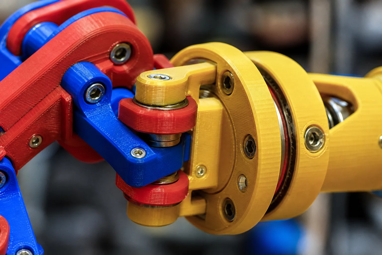
High-precision robotics assemblies impose severe demands on small-batch additive manufacturing. In this prototyping cycle, forty articulated joint assemblies comprising bearing seats, planetary gear housings, and structural links were manufactured using carbon-fiber-reinforced polyamide (PA12-CF). The primary objective was establishing whether additive prototyping could deliver the tight radial clearances (±0.035 mm) required for smooth actuator coupling without post-machining operations.
Measurement passes were executed using coordinate measuring machines (CMM) and digital bore micrometers across all forty iterations. The metrology evaluation focused on concentricity across bearing housings, planar warp along mounting faces, and thermal shrinkage differentials between early-batch prints and end-of-run parts. Data indicated that thermal chamber stabilization within the first 45 minutes of machine operation directly determined whether parts met the kinematic clearance envelope.
Fieldbook Inspection Benchmark
Statistical process control relies on repeatability across all batch specimen samples rather than a single ideal part. Ensure consistent thermal bed calibration and optical micrometer zero-points before taking measurement passes.
Process Variation Breakdown
Dimensional dispersion analysis identified two key variance vectors across the run: build plate position gradient and inter-layer cooling rates on tall vertical flanges. Parts placed within the central 60% of the build envelope demonstrated standard deviations below 0.012 mm, whereas peripheral components exhibited outward thermal contraction of up to 0.048 mm. Modifying build spacing and applying symmetrical chamber pre-heating brought the overall process capability index (Cpk) to 1.44.
- Bearing housing inner diameter sustained at 28.000 mm (+0.025 mm / -0.010 mm) across central plate clusters.
- Flange face perpendicularity maintained within 0.04 mm across all 4-axis structural hinge mounts.
- Inter-layer shear strength and torque tolerance verified through dynamic 12 Nm cyclic stress load tests.
Interactive Tolerance & Batch Matrix
Live parameter verification module
Inspection Peer Reviews & QC Logs
Field measurements submitted by metrology specialists
Submit Field Inspection Comment
Record dimensional observations or variance queries for this item.